Electrans Projects
Below are the two main projects I worked on during my internship. The first involved designing a custom bed of nails test fixture for a CAN board. I created a custom control PCB using Altium to perform power tests, CAN tests, and resistance checks. Alongside this, I used a Raspberry Pi 4 to write a PyTest script that ran a series of tests and logged the results in a Google Sheets database.
The second project, which evolved through several stages, addressed the problem of drivers forgetting to raise the boom on a truck, leading to significant system damage. After several iterations of accelerometer R&D attempting to record precision angles, we ended up implementing a proximity sensor and sheet metal solution.
Bed of Nails Test Fixture
This was the primary project during my internship. A business-critical CAN PCB needed to be tested at scale, and I was tasked with designing and building the bed of nails test fixture to accommodate each unit. The project consisted of three key components:
- Mechanical: The pressing mechanism, the enclosure, and ensuring a smooth user experience.
- Electrical: The design of a custom control PCB with pogo pins, routing appropriate power to the enclosure, and selecting the right computer interface.
- Software: Choosing a testing framework and writing scripts to assess the functionality of the CAN board.
This project was an excellent fit for me, as my focus is on mechatronic test equipment design. I was excited to design the custom PCB and write the necessary software to conduct the tests. A primary goal was to ensure an exceptional user experience and make the fixture modular, so that minimal adjustments would be needed when testing different PCBs.
I selected an off-the-shelf enclosure from McMaster-Carr for its simplicity and cost-effectiveness. The enclosure is also future-proofed, being larger than required for current needs, which allows for potential additions in the future. I made the center plate 3D printable so that it can be easily swapped out for testing different PCBs. Additionally, the pressing plate is 3D printed to prevent damage to components on the device under test (DUT) and allow for complex geometry of the mechanism at a low cost.
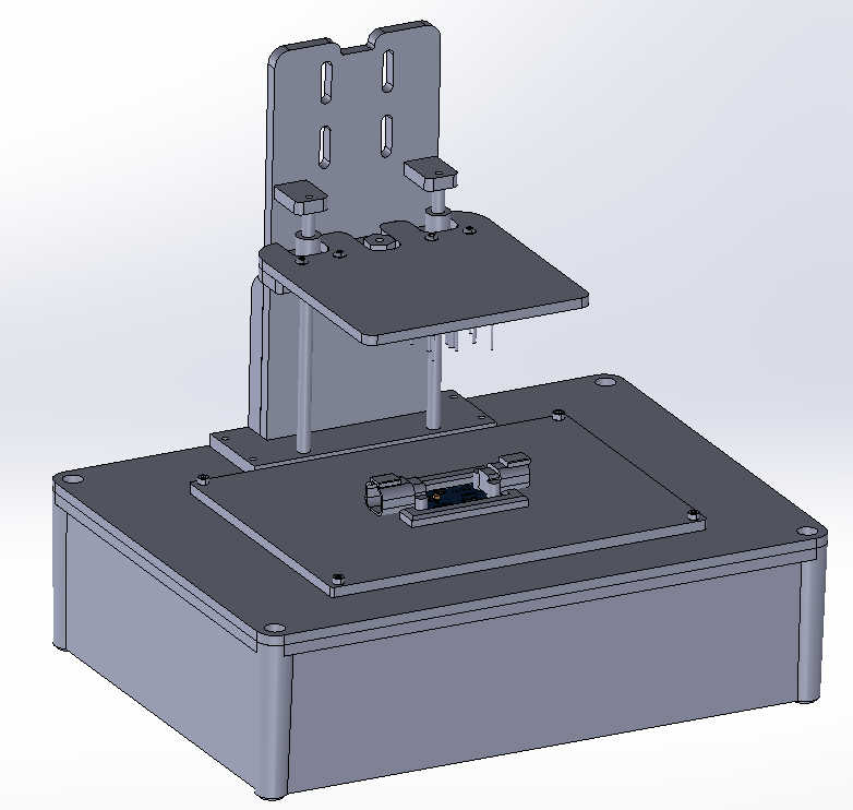
Fixture with Press Up
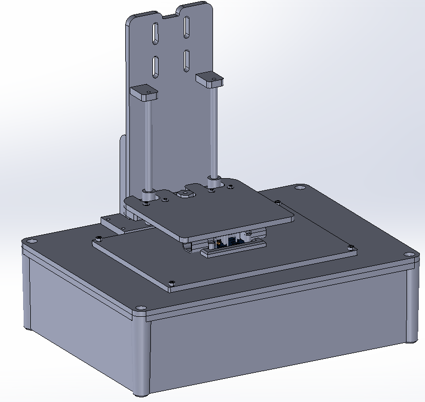
Fixture with Press Down
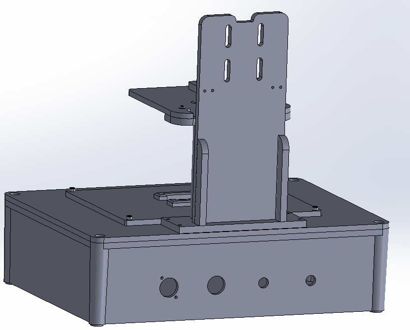
Back of Fixture
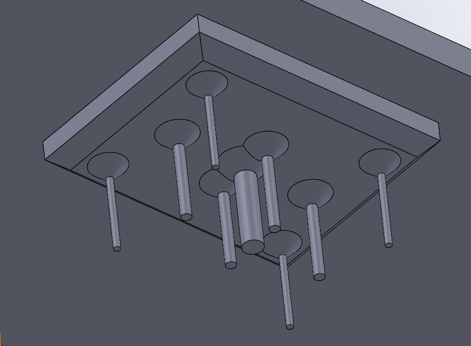
Pressing Plate
Cross Section
PCB Holder
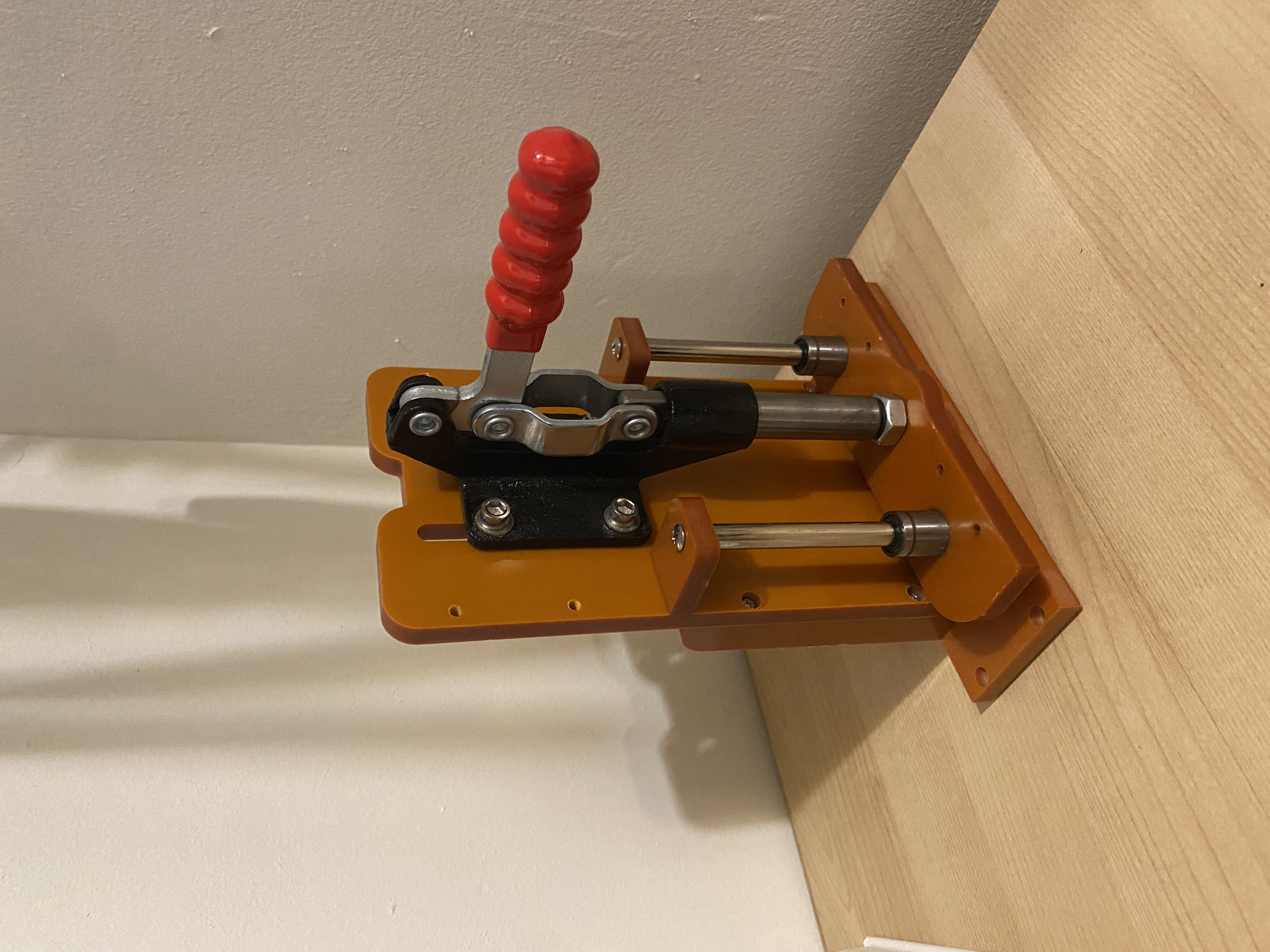
Pressing Mechanism
The next step in the project was designing a pogo pin control board that needed to:
- Support +/-12V power testing capabilities.
- Perform CAN bus termination resistance checks.
- Enable CAN communication.
The board also needed to interface with a Raspberry Pi 4, functioning similarly to a hat. The design of the PCB, including schematics, layout, and final 3D views, was done in Altium. At the time of writing, the PCB is in the manufacturing stage, and I will update this section with real-world images once they are available.
Download PDF of Schematics and 2D Layout
Top Level

Power
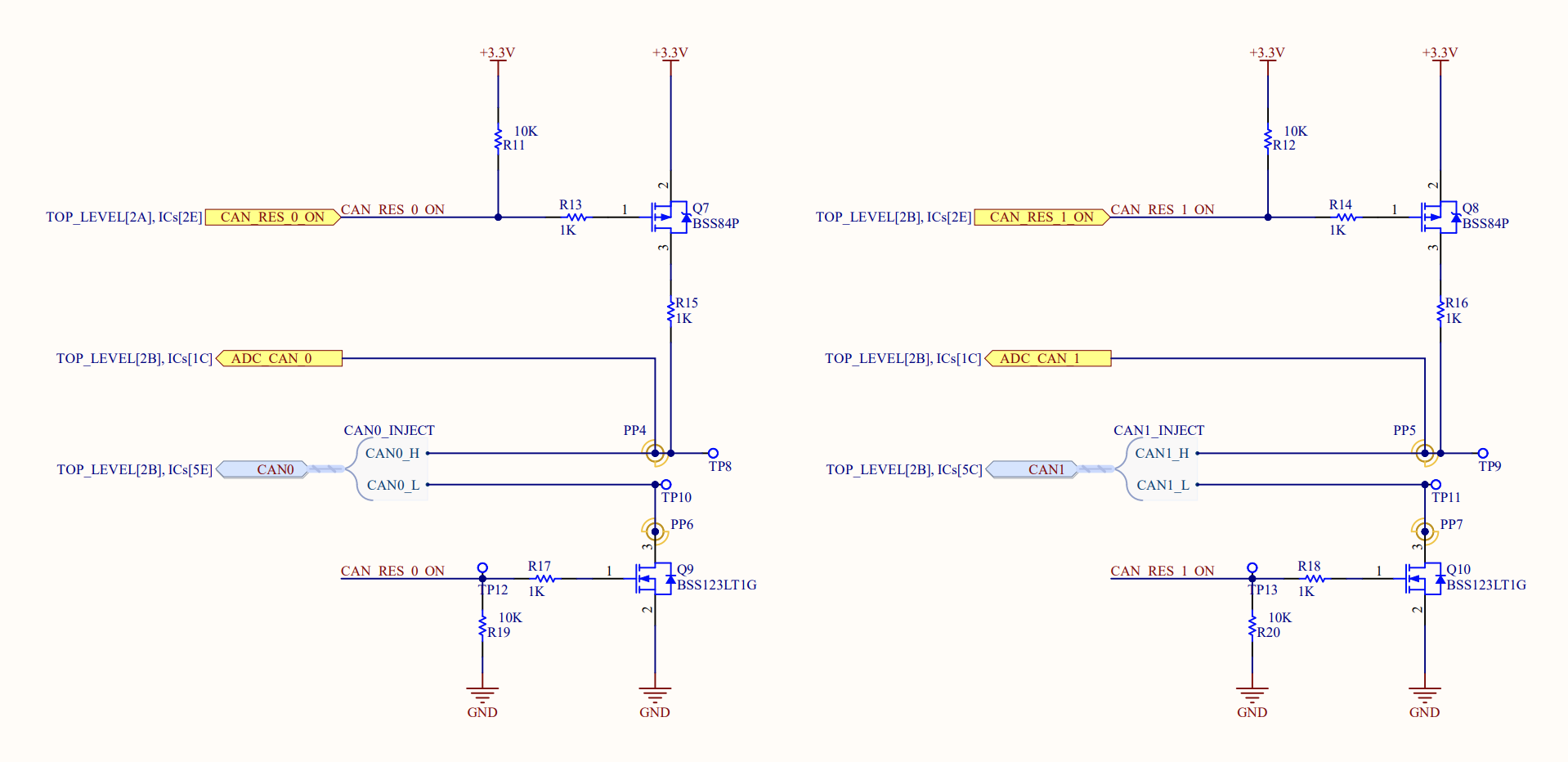
CAN Resistance Sense
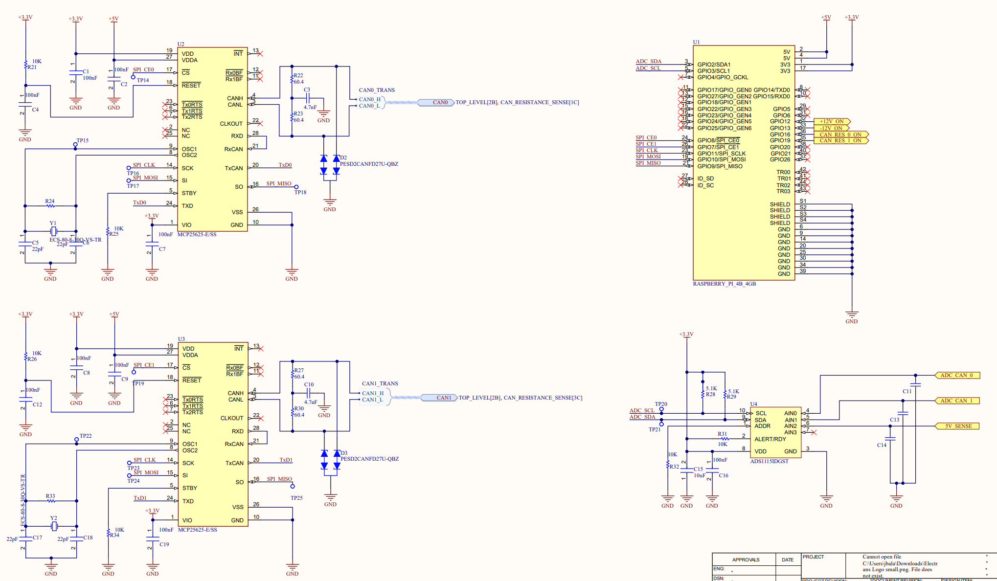
IC's
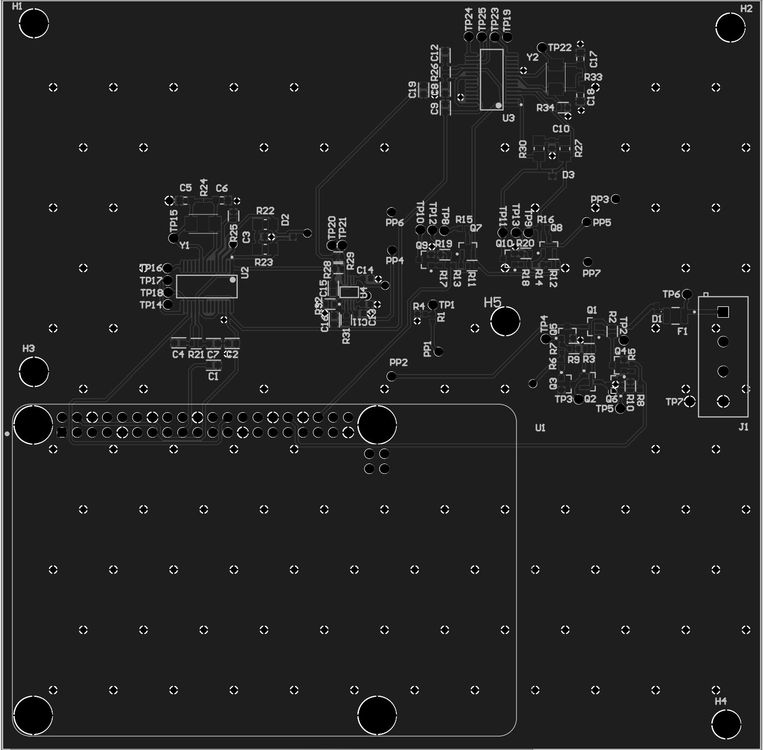
2D Layout
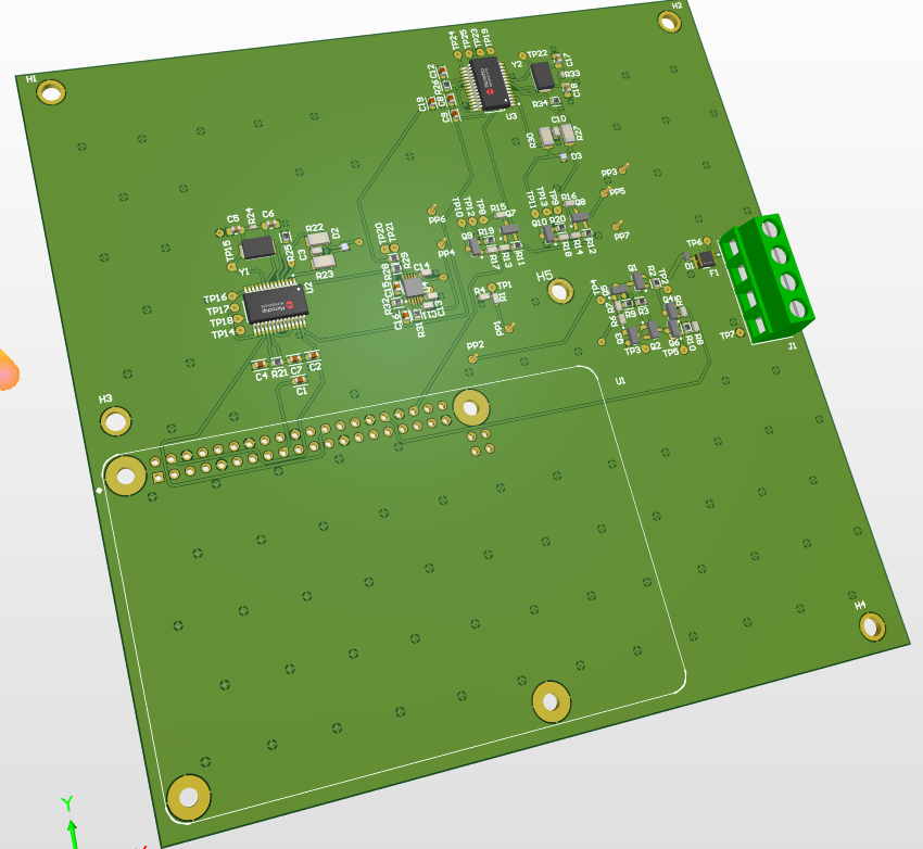
3D view of PCB - Front
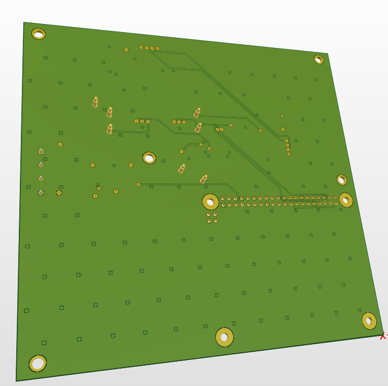
3D view of PCB - Back
The software component of this project was both the most exciting and the most challenging for me. I chose Pytest for its robust documentation and ease of use, which would help me move quickly. I knew I would need to develop the software efficiently, and Pytest's error tracking capabilities were a significant advantage since each PCB test generates a record for future reference. This software runs on the Raspberry Pi 4 and interfaces with the control PCB. While I may eventually upload the code to my GitHub, it may contain sensitive information, so I will need to be cautious.
Autonomous Boom Control
When connecting certain trailers, the system on our trucks risked being crushed if the driver didn’t raise the boom high enough. To address this issue, we aimed to automate the boom-raising process. The project started as a poorly defined problem, and unclear requirements led to unnecessary iterations and delays before reaching a solution.
The primary success criterion was to maintain a minimum angle of 2 degrees between the truck and trailer to prevent system damage, without exceeding 10 degrees to avoid unnecessary boom raising. Initially, I proposed a straightforward binary system: if the angle exceeded 5 degrees (2 degrees plus a safety margin), no action was required. If the angle fell below 5 degrees, the system would raise the boom until the threshold was reached.
However, there was a decision to measure the angle in real-time with a ±0.5-degree accuracy, a requirement that shifted multiple times during development. This approach proved challenging, requiring high-quality sensors, reliable data acquisition, and additional time to develop robust code. I originally set up a 3-axis analog accelerometer (ADXL 335) as a proof of concept, with a relay board to switch control between the system and the user. Using an Arduino Uno, I wrote code that applied a smoothing algorithm over the last 20 accelerometer samples. Also, I mounted these sensors at approximately a 45 degree angle since during my calibration against measured angles, I found that the sensors were most accurate in the 35-55 degree range.
Testing on the truck included nine test cases ranging from static conditions to driving over bumps while raising the boom. I repeated the tests on two separate days with a 15°C temperature difference. The prototype achieved an accuracy of ±0.5 degrees, meeting the original requirements. I did come across some EMI issues since the long run of unshielded wire acted as attena's, so I ordered shielded wire for the next series of testing. However, despite meeting the criteria, the team required an even higher accuracy of ±0.1 degrees, which I found unnecessary and difficult to justify.
To meet the new demands, I switched to the Murata SCA830-D07, a single-axis automotive SPI accelerometer. While exploring an upgrade to a 9-axis BNO055 IMU for potential benefits like easier calibration, we ultimately rejected it due to increased complexity. Since no breakout board existed for the Murata sensor and we were facing many issues during the first few hours of testing, I designed a custom PCB to streamline troubleshooting and testing, eliminating uncertainties from soldering, component failures, or coding issues.
During the breakout board schematic review, another system failure occurred, damaging a unit. This prompted a pivot to a simpler binary solution using an inductive proximity sensor already in use elsewhere on the system. I designed two sheet metal brackets: one to mount the sensors and the other to serve as the "target" bracket for the sensors.
To ensure the target bracket height was accurate, I verified that when the boom raised and the sensors passed above the top of the target bracket, the sensor signal went low, indicating the 5-degree threshold had been met. I repeated the same process for the 8-degree threshold to verify redundancy. The solution was tested, and a video demonstrating the functionality is included below! The prototype was accurate to +/- 0.5 degrees and was only tested in a static condition because at the time, we were not able to drive the truck. Vibrations were a concern, so we added bracing and ordered some prototypes to do further testing in different conditions.
We abandoned the strict ±0.1-degree requirement and changed it to ±1.5 degrees, opting to focus on immediate system protection. The sensors were mounted to the second sheet metal bracket, which was mounted to existing holes on the truck, and connected to an ECU that interfaced with the boom control pump via CAN messages. This solution was simpler, cheaper, and more robust, allowing for rapid deployment without the need for additional enclosures or mounting solutions for the accelerometer.
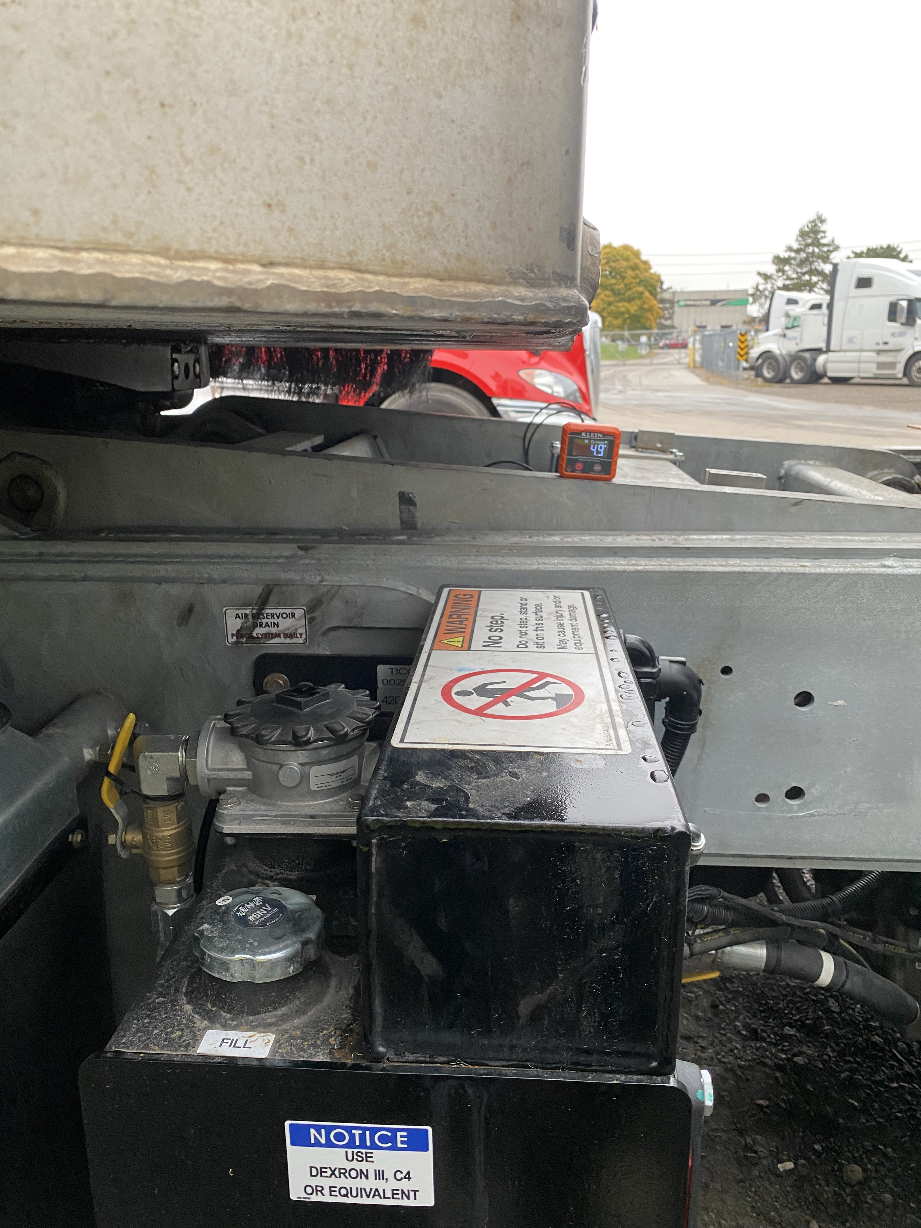
This experience reinforced the importance of challenging overly complex requirements and keeping designs simple. Below are pictures of the initial 3-axis accelerometer tests, the final sheet metal solution, and the prototype in action.
While I focused on the mechanical portion of the solution, the lead electrical engineer handled the dashboard controller PCB design due to the tight timeline. The controller determined whether the system or the driver controlled the boom, with safety measures ensuring default control reverted to the driver if power was lost or an error occurred. The final system integrates seamlessly into existing trucks, using existing mounting points and CAN communication to prevent crushing issues effectively.
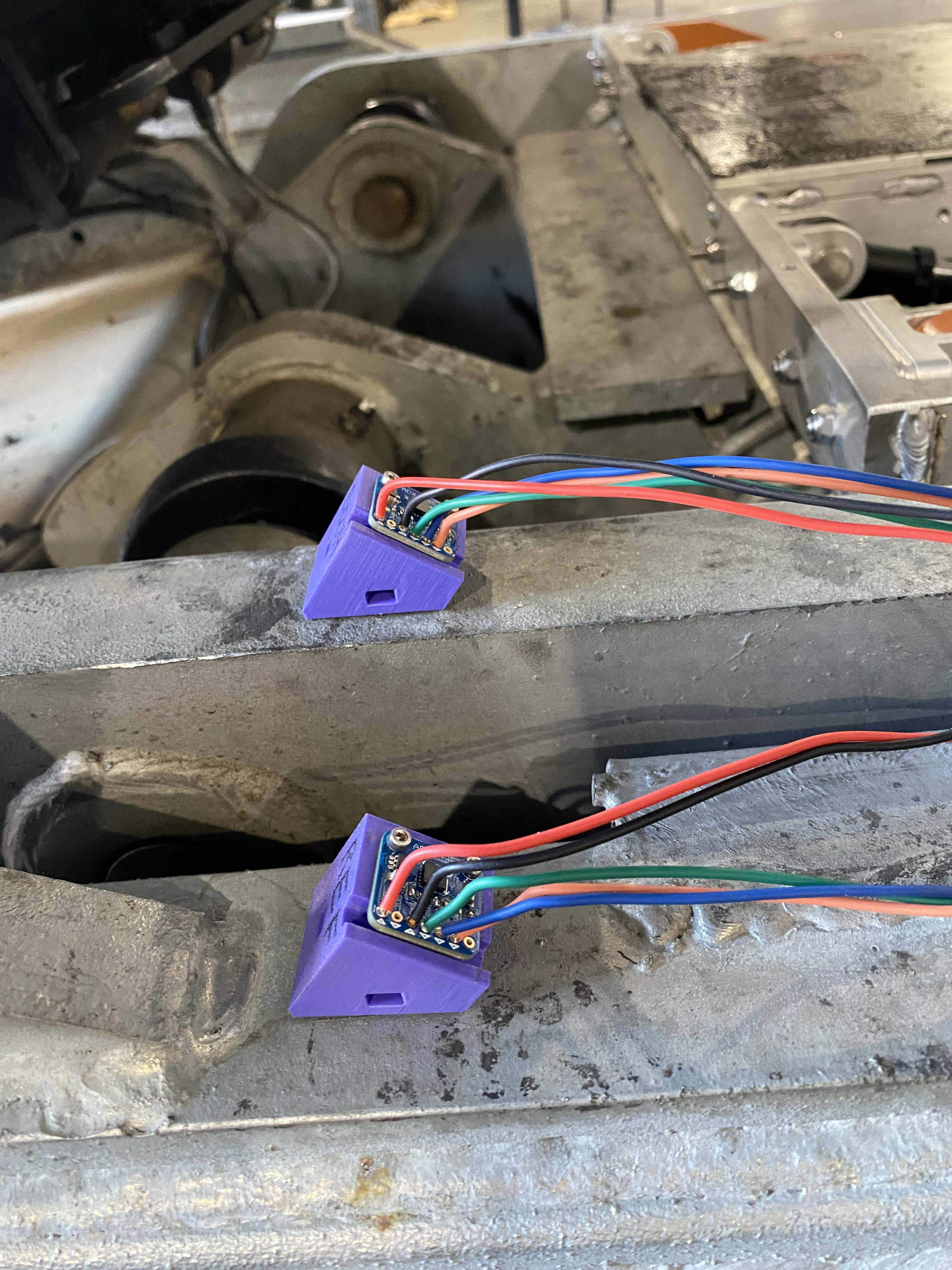
3 axis analog accelerometers up close
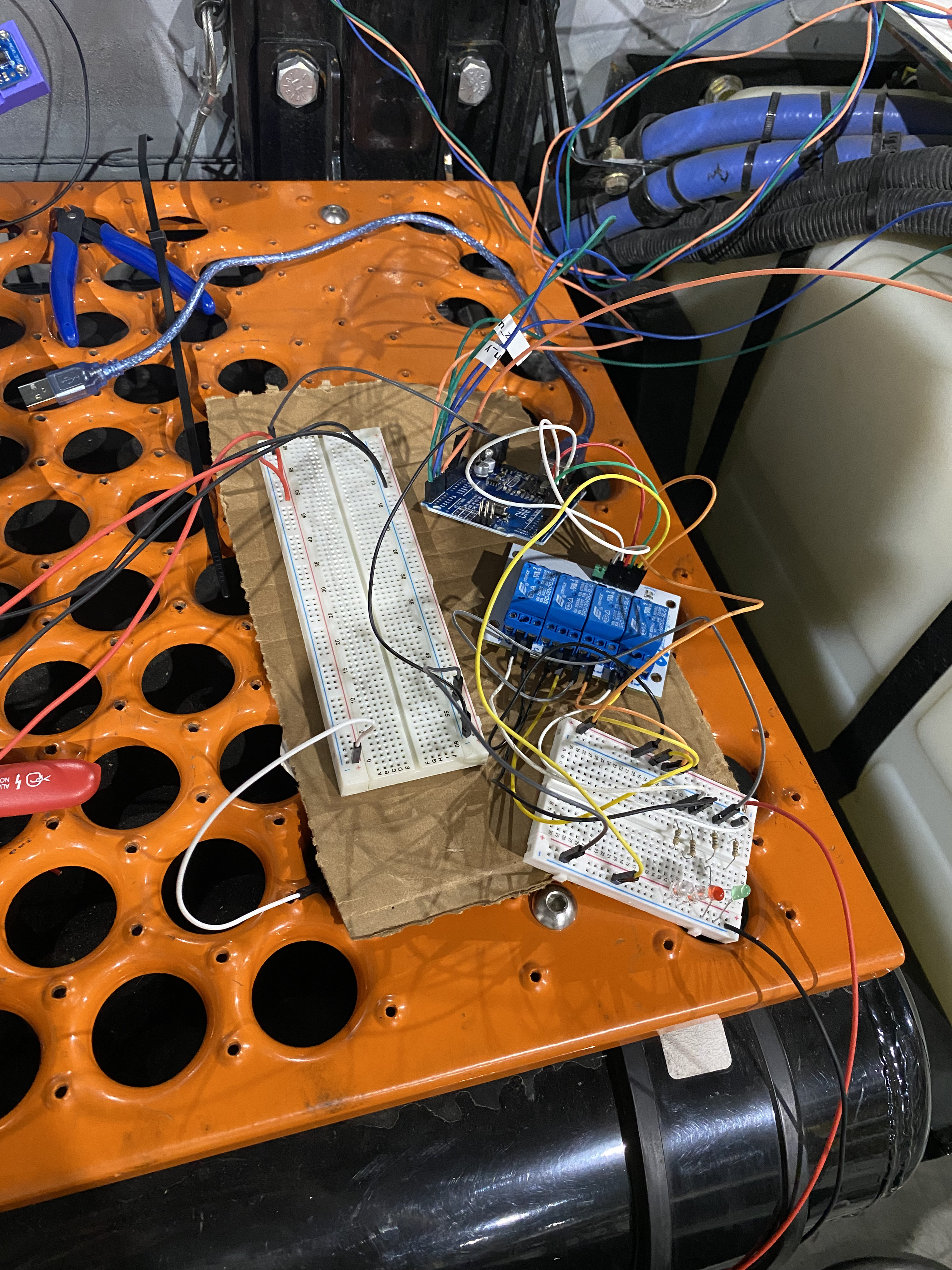
3 axis analog accelerometers with relay board
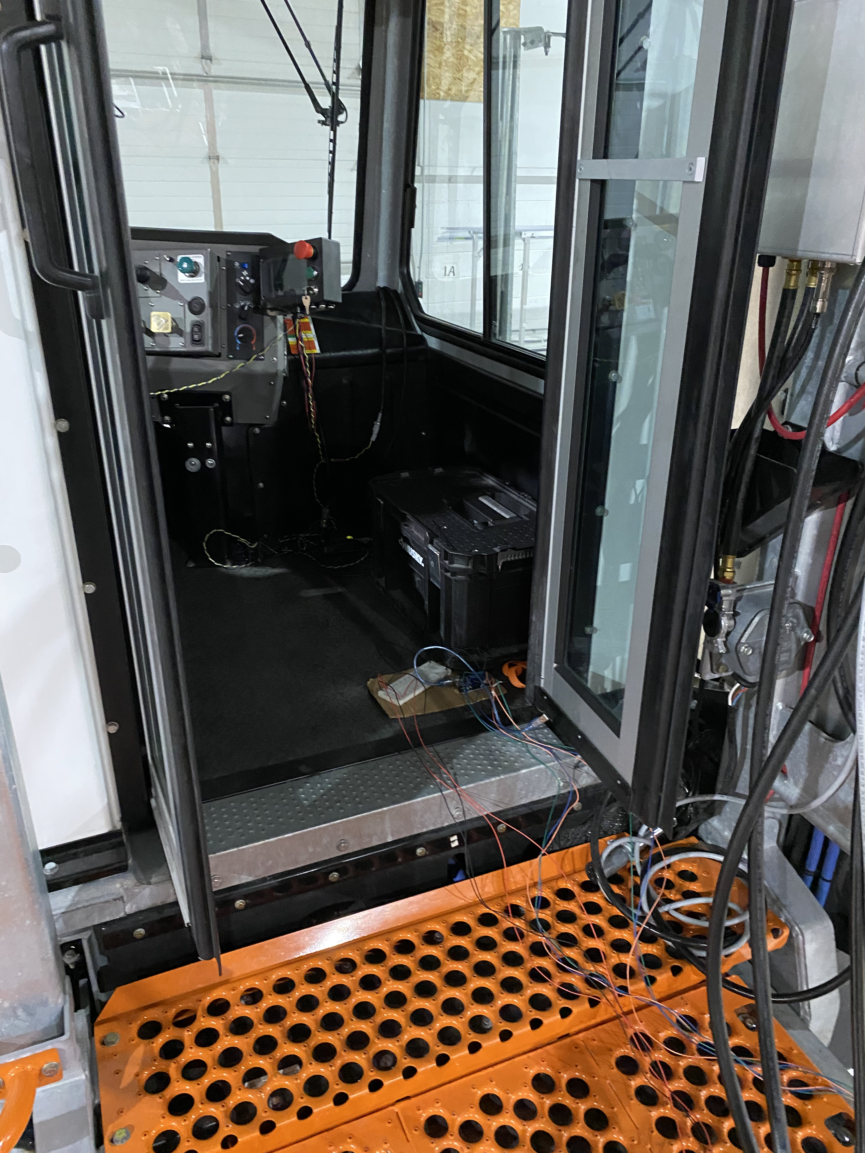
Testing setup in truck
3 axis analog accelerometers with boom moving during prototype testing
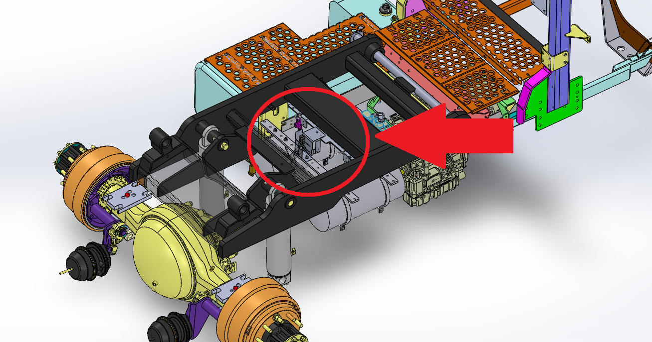
Inductive proximity sensor mount - CAD zoomed out
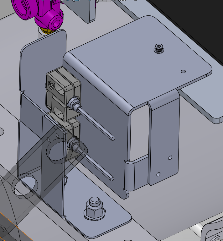
Inductive proximity sensor mount - CAD zoomed in
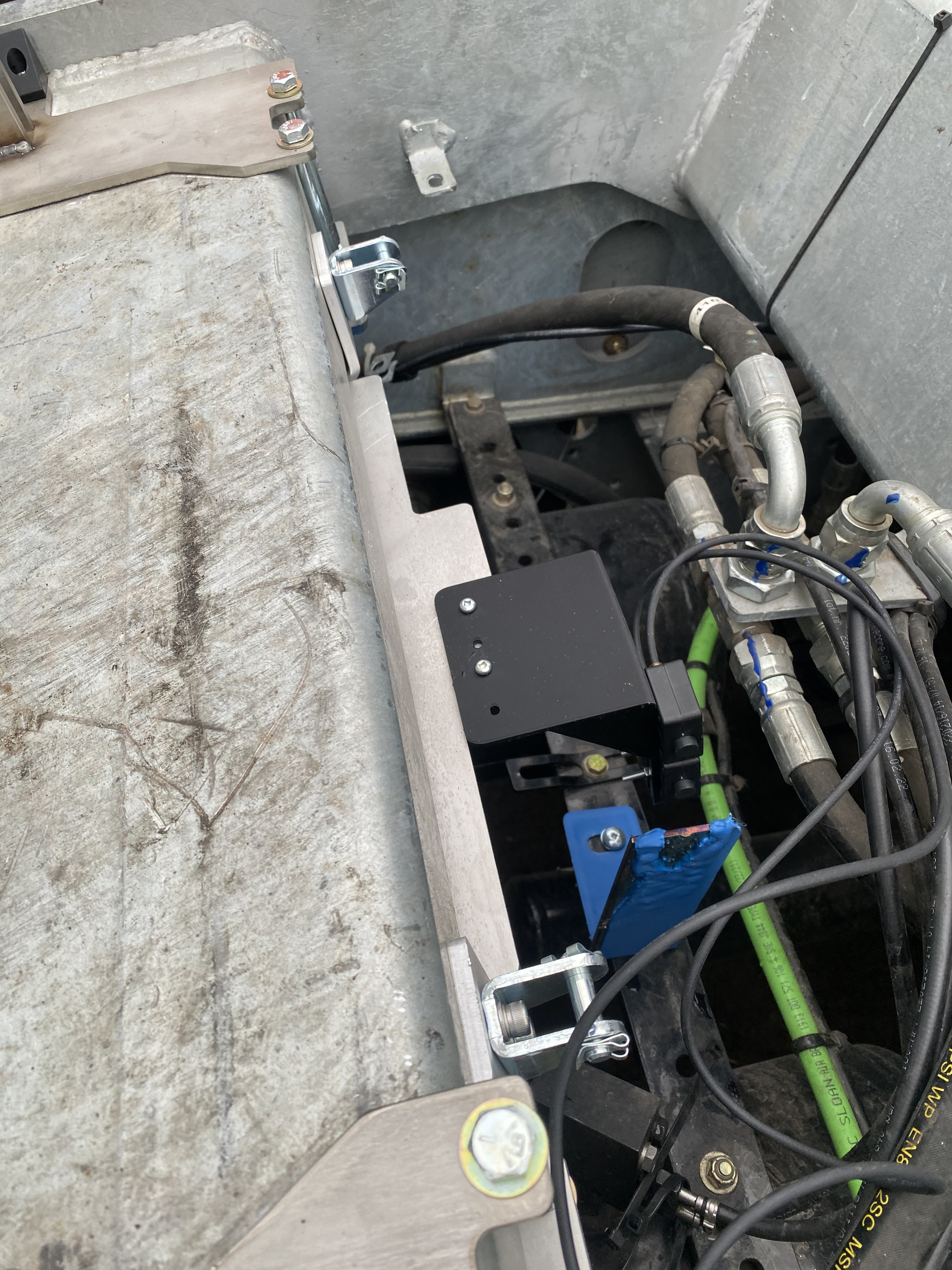
Inductive proximity sensor mount - prototype mounted IRL side view
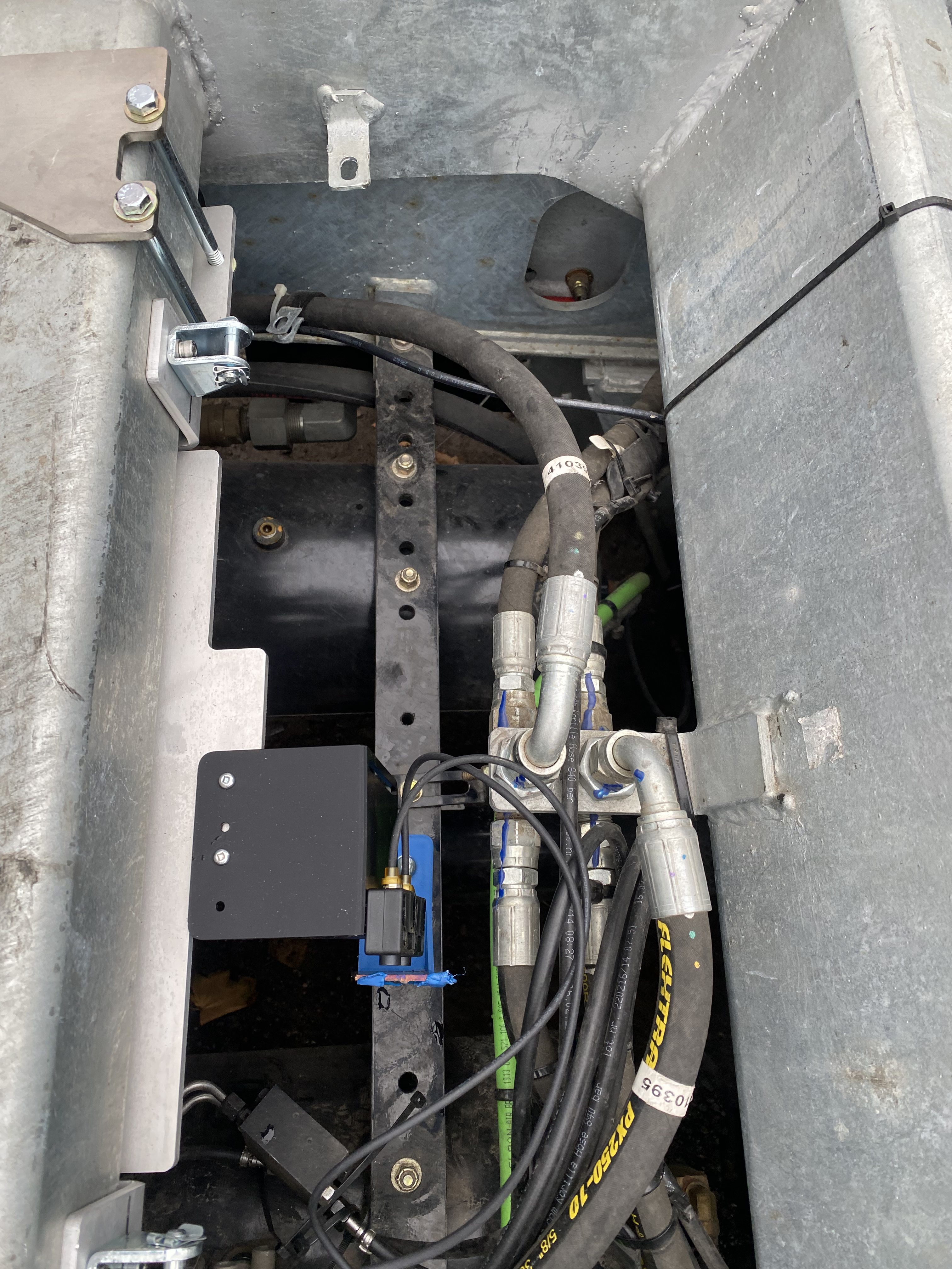
Inductive proximity sensor mount - prototype mounted IRL top view
